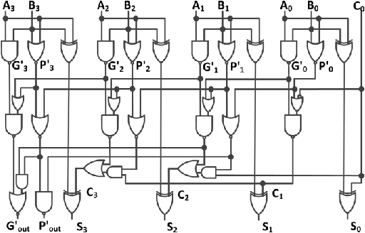

4 bit adder diagram full#
The adders described in this module are generally called Ripple Carry Adders because of the way that the carry bit is propagated from one stage of the adder to the next, rippling through the chain of full adders until the carry out is produced at the carry out pin of the final stage.
4 bit adder diagram software#
Overflow errors can be corrected, but this would require either some additional electronics or a software action in response to the overflow signal. To check this, the correct answer (although still with the wrong sign) could be obtained if, noting that an overflow had occurred, the answer was complemented and 1 added, giving an unsigned binary result of 10001000 2 which converts to 128 + 8 = 136 10. In this case adding −63 10 and −73 10 should have produced a negative result of −136 10 and not +120 10. Table 4.1.8 shows that adding two negative values can also produce a change in sign and a wrong twos complement result if it is greater than −128 10. The result of adding two positive numbers has produced a correct positive result with no carry and no overflow. Table 4.1.4 shows the effect of adding two positive values where the sum is within the range that can be held in 7 bits (≤127 10). When the carry in (C IN) and carry out (C OUT) bits of this adder are examined, it can be seen that if an overflow has occurred C IN and C OUT will be different, but if no overflow has occurred they will be identical. 4.1.5 the overflow detection system consists of a single exclusive or (XOR) gate that takes its inputs from the carry in and carry out connections of the bit 7 (sign bit) adder. To overcome this problem, it is necessary first to detect that an overflow problem has occurred, and then to solve it either by using additional circuits or, in computing, by implementing a corrective routine in software.įortunately there is a quite simple method for detecting when an overflow occurs. Therefore the result will need to occupy one extra bit, which means that the calculated value will ‘overflow’ into bit eight, losing a major part (128 10) of the value and changing the sign of the result. 4.1.4, when adding either positive or negative 7-bit values, the result could be larger than 7 bits can accommodate. No matter what the word size of a digital system (8-bits 16-bits 32-bits etc.), a given number of bits can only process numbers up to a maximum value that can be held in its designed word length.ĭuring arithmetical operations it is possible that adding two numbers (with either positive or negative values) that are both within the system’s limit, can produce a result that is too large for the system’s word length to hold.įor example, in a twos complement adder such as shown in Fig. In this system the most significant bit (bit 7) is not used as part of the number’s value, it is used to indicate the sign of the number (0 = positive and 1 = negative). 4.1.4 is designed to add or subtract 8−bit binary numbers using twos complement notation. The 8-bit adder/subtractor illustrated in Fig. (Here + signifies addition rather than OR)Īlternatively, if addition of A and B is required, then the control input is at logic 0 and number B is fed to the adder without complementing. The logic 1 on the control input is therefore also fed to the first carry input of the adder to be included in the addition, which for subtraction is therefore: with its value represented by the lower 7 bits (bit 0 to bit 6) and the sign represented by the most significant bit (bit 7). The result of this will be an 8-bit number in twos complement format, i.e. Twos complement subtraction in an 8-bit adder/subtractor requires that the 8-bit number at input B is complemented (inverted) and has 1 added to it, before being added to the 8-bit number at input A. When subtraction is required, the control input is set to logic 1, which causes the bit at any particular B input to be complemented by an XOR gate before being fed to input B of the full adder circuit. 4.1.3 but subtracts using the twos complement method described in Digital Electronics Module 1.5 (Ones and Twos Complement). This circuit adds in the same way as the adder in Fig. This is an 8-bit parallel adder/subtractor. A further development of the parallel adder is shown in Fig.4.1.4.


To carry out arithmetic however, it is also necessary to be able to subtract. 4.1.4 8−Bit Twos Complement Adder/Subtractor.


 0 kommentar(er)
